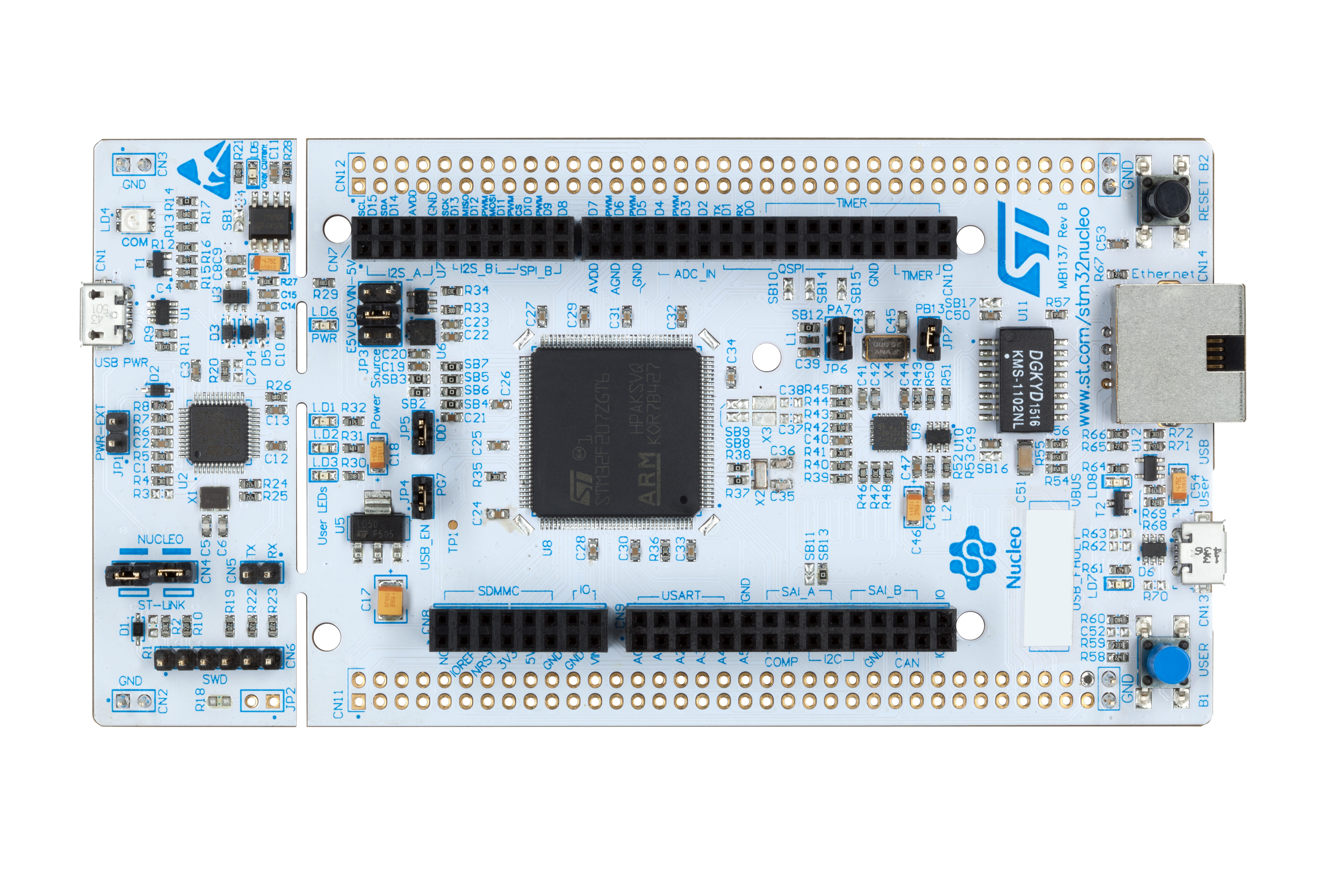
#OPENSTM STM32CUBEMX NUCLEO F401RE CODE#
Your code makes a single conversion with an interrupt triggered when it's complete, then reads and stores the value, and only then instructs the ADC to start the next conversion, introducing a variable delay that depends on a couple of hard to predict factors. Considering the ridiculous amount of overhead in HAL, it seems realistic.
#OPENSTM STM32CUBEMX NUCLEO F401RE FULL#
Looking at the plot you've attached it looks like the actual sampling frequency is 300 kHz (there are 30 samples in a full cycle of the 10 kHz signal), that's 3.33 µs, or 25200 clock cycles. When the core is running at 84 MHz, that's one sample every 60 core cycles.Ħ0 cycles are barely enough to even start executing an interrupt handler, with flash wait states taken into account.

Sampling time is 3 cycles, conversion time at 12 bits resolution is 12 cycles, so the sampling frequency of the ADC is = 1.4 MHz ( 21/(12+3)). I'm assuming that the 21 kHz is a typo, and the ADC is running on APB2/4 = 21 MHz. Plot of values for input frequency range of 1- 200Khz Void assert_failed(uint8_t *file, uint32_t line) If (HAL_ADC_ConfigChannel(&hadc1, &sConfig) != HAL_OK) SConfig.SamplingTime = ADC_SAMPLETIME_3CYCLES **Configure for the selected ADC regular channel its corresponding rank in the sequencer and its sample time. **Configure the global features of the ADC (Clock, Resolution, Data Alignment and number of conversion) If (HAL_RCC_ClockConfig(&RCC_ClkInitStruct, FLASH_LATENCY_2) != HAL_OK) RCC_ClkInitStruct.APB2CLKDivider = RCC_HCLK_DIV1 RCC_ClkInitStruct.APB1CLKDivider = RCC_HCLK_DIV2 RCC_ClkInitStruct.AHBCLKDivider = RCC_SYSCLK_DIV1 RCC_ClkInitStruct.SYSCLKSource = RCC_SYSCLKSOURCE_PLLCLK |RCC_CLOCKTYPE_PCLK1|RCC_CLOCKTYPE_PCLK2 RCC_ClkInitStruct.ClockType = RCC_CLOCKTYPE_HCLK|RCC_CLOCKTYPE_SYSCLK If (HAL_RCC_OscConfig(&RCC_OscInitStruct) != HAL_OK) RCC_OscInitStruct.HSICalibrationValue = RCC_HSICALIBRATION_DEFAULT RCC_OscInitStruct.OscillatorType = RCC_OSCILLATORTYPE_HSI

**Initializes the CPU, AHB and APB busses clocks _HAL_PWR_VOLTAGESCALING_CONFIG(PWR_REGULATOR_VOLTAGE_SCALE2) **Configure the main internal regulator output voltage * Initialize all configured peripherals */

* Reset of all peripherals, Initializes the Flash interface and the Systick. Void HAL_ADC_ConvCpltCallback(ADC_HandleTypeDef* hadc) Below is my code and plot of values for input frequency range of 1- 200Khz sine wave. ADC is of 12 bit resolution with 3 sampling cycles ADC clock frequency is 21Khz. The code does not work beyond 10kHz of input signal. I have programmed the ADC using interrupts store about 10,000 values in an array and read them using a. I am using the ADC on NUCLEO- STM32F401RE board.


 0 kommentar(er)
